Synchrotron radiation and Synchrotron light sources
Written by: Giammarco Nalin
March 30, 2020
Research on light-matter interactions has been flourishing during the last century, yielding fundamental contributions to the understanding of Nature [1]. As our understanding of the physical aspects of nature becomes more complex, the need for better probing tools is more prevalent. The rapid of growth of photonics, since the early observation of X-rays by Wilhelm Röntgen in 1895, is astonishing, both from the theoretical and the engineering points of view [2], leading to the first reported observation of synchrotron radiation (SR) in 1948 [3]. This presented the scientific community with a new technique to perform experiments in many regions of the electromagnetic spectrum, starting from X-rays (hard and soft), infrared (IR), to visible and ultra-violet (UV) ranges with unprecedented flexibility and probe intensity. According to the Planck-Einstein fundamental relation E=ℏω:, there is a direct proportionality between the energy, E, and the wavelength, ω, of a photon through the (reduced) Planck’s constant . This means that photons with energy from 10 to 10 keV have a wavelength of between 100 nm to 0.1 nm, respectively, and can interact with objects of similar characteristic dimensions, as shown schematically in Figure 1.
Almost all fields of science have greatly benefitted from the availability of bright X-ray radiation. Among the most remarkable ones are not only condensed matter physics, materials science, biology and medicine, but also geology, non-destructive techniques and cultural heritage. Some examples have a tremendous impact on society, such as nano-materials, in-situ catalysis, energy storage, high-pressure research, polymer research, mesoscale bioscience and protein factories. The most commonly used techniques are related to diffraction and scattering for imaging (X-ray diffraction XRD, small-angle X-ray scattering SAXS, grazing-incidence small-angle X-ray scattering GISAXS and X-ray reflectivity XRR) and spectroscopy (X-ray absorption spectroscopy XAS, X-ray absorption near-edge structure XANES, extended X-ray absorption fine structure EXAFS, X-ray magnetic circular dichroism XMCD, X-ray photoelectron spectroscopy XPS and angle-resolved photoemission spectroscopy ARPES). The impact on scientific knowledge has been an immense and an exhaustive review goes beyond the scope of this article. For more details see [7-12].

Figure 1: Sketch of the electromagnetic spectrum showing the broad distinction of photon wavelengths (inversely proportional to frequencies). The different regions of the spectrum are illustrated with an example of an object with a characteristic dimension similar to the average wavelength of that region. The regions of interest for the synchrotron light source facilities are the visible, ultraviolet (UV) and X-Ray (usually divided between soft and hard), with energy in electronvolts (eV) of 1 to 50 eV, 50 to 500 eV and 500 to 50000 eV, respectively. [Image downloaded from Wikipedia.com in January 2020].
In a synchrotron light facility, electrons travelling close to the speed of light are manipulated using special magnets to promote the emission of a flux of photons called the synchrotron radiation (SR). SR spans a broad range of wavelengths, from the visible to hard X-rays, each with very high brilliance. The brilliance is the number of photons emitted per second, per angular direction, per specific range of frequencies. SR is usually several orders of magnitude brighter than other sources, as Figure 2 shows.
SR generation, a brief introduction to its core characteristics and a description of a general scheme for a synchrotron light facility are the main topics of this blog. The importance of this subject becomes apparent, knowing that today more than 50 synchrotron facilities exist all over the world. These facilities are regularly used by a community of approximately 20000 scientists, contributing to scientific knowledge with a volume of more than 40000 publications during the period of 2013-2017 alone [4].
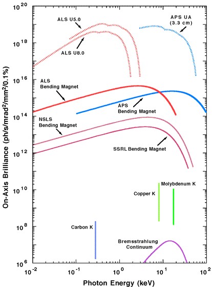
Figure 2: Brilliance of emitted photons represented as a function of the energy of the emitted photon for different sources. The photon energy spans from UV (10^1 eV) up to hard X-Rays (10^5 eV). In the lower part of the graph, the vertical lines are atomic emissions and the bremsstrahlung to the continuum is typical for X-Ray tubes; all are restricted to a small range of wavelengths with low brilliance. In the upper part, all SR sources (bending magnets) are sketched. The emissions, compared to the other sources, are several orders of magnitude higher and for a broader set of frequencies (not the double logarithmic scale). At the relative maximum of each curve, it is possible to locate the critical wavelength λc; half of the radiated power is radiated below λc, the other half above. Usually, the peak photon flux is found close to λc and the useful flux extends to ~λc /10. [Image from “Synchrotron radiation facilities” by John R. Helliwell, Nature Structural Biology volume 5, pages 614–617 (1998)]
Historically, the SR has been an unwanted by-product in particle accelerators. In particle accelerators, heavy, charged particles, such as protons or ions, are accelerated to relativistic speeds to perform collisions manipulated with magnets to guide them, decreasing their energy severely. This “wasted” energy is emitted in the form of SR (bremsstrahlung), but there was no practical usage of the SR in facilities designed for particle acceleration. The first SR was observed using an instrument called a cyclotron in the synchronisation mode. This instrument is capable of accelerating electrons at relativistic and ultrarelativistic speeds. Indeed, the name “synchrotron radiation” comes from the type of accelerator used when this phenomenon had been observed for the first time. Early experiments on SR took place at particle acceleration facilities in the so-called “parasitic mode”, where extra holes were drilled at the bending magnets to extract the SR [5]. The second generation of synchrotron light facilities, available from the early ’80s, was built to carry out fundamental research primarily with SR; the current, third-generation facilities, in operation since the middle ’90s, are built on an industrial scale and, therefore, provide many science and industrial sectors with access to exploit SR for innovation. The fourth generation facilities are currently under development and, in parallel, the free-electron LASERs (FELs) have been developed to improve the spectral resolution, to enhance the brilliance and shorten the pulse duration of the emitted radiation [6].
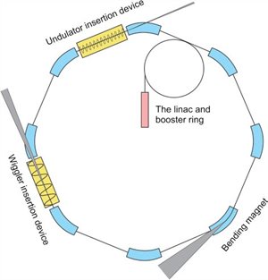
Figure 3: The main sections of a synchrotron facility. The red block represents the LINAC, connected to the boosting ring. The blue blocks represents the bending magnets. The yellow blocks depict two insertion devices: undulator and wiggler. The grey triangles represent the SR, with an aperture proportional to its relative collimation. An undulator can also be located outside the storage ring, along a beamline. It is relevant to note that the storage ring is composed of straight sections between the bending magnets; this maintains the electrons on the circular trajectory.
[Image downloaded from https://media.journalism.berkeley.edu/projects/2015/20150911_bootcamp2/als/ in January 2020, Illustration by J.-F. Santarelli]
Before touching upon the role of relativity in a radiative process of accelerated charges, it is essential to depict a standard set-up of a synchrotron light facility, as the one outlined in Figure 3. Common to all types of facilities is the presence of ultrarelativistic electrons in a vacuum (divided into bunches), which are kept circulating on a quasi-circular trajectory with the use of various types of bending magnets. According to Maxwell’s equations, a charged particle is a source of an electric field. A particle of charge, q, with velocity, v, moving in a magnetic field, B, is accelerated by the Lorentz force F= qE + qv × B, where the force, F, acts on the particle modifying its trajectory. In particular, when a strong magnetic field is applied orthogonally to the propagation direction of a particle (e.g. electrons), an intense transversal acceleration arises, the electromagnetic (EM) field lines are curved and the particle radiates. This electromagnetic radiation propagates with the finite speed of light and is called a photon. A photon is a quantum of the EM field.
Generally, electric fields are used to accelerate and tune the kinetic energy of electrons, while magnetic fields are used to modify the electron's trajectory by introducing a perpendicular acceleration to the electron propagation direction (i.e. a transversal momentum). The electrons emerge from an electron gun and are modulated into bunches. The first acceleration occurs in a linear accelerator (LINAC) by applying a series of strong electric fields parallel to the propagation direction of the electrons. The LINAC is constituted by a series of radiofrequency (RF) cavities, which increase the electron velocity close to the speed of light by using strong electric fields. Despite the very high velocity, electrons at this stage still have a kinetic energy, Ek,of tens to hundreds of MeV, which is not optimal for SR application. Then the electrons are injected into the booster ring, a circular device composed of a custom RF cavity and several powerful bending magnets; the cavity is used to accelerate the electrons further, while magnets are used to keep the electrons on a circular trajectory until they reach the desired extraction kinetic energy, usually a few GeV. Finally, the electrons reach the storage ring, a quasi-circular device, where the desired SR is generated. The ring is kept at ultra-high vacuum (UHV) around 10-9 mbar pressure to avoid scattering of the electron bunches with the residual gas, thus reducing the loss rate of electrons. Along the storage ring, there are several more RF cavities and bending/correcting magnets. The RF cavities boost the electron’s Ek in a similar way to a LINAC and the booster ring, to restore the Ek that is lost due to magnetic bending. Bending magnets impose and maintain the trajectory of the electrons. Several types of magnets are implemented: dipole magnets are used to keep the trajectory, quadrupoles are used as electromagnetic focussing lenses, sextupoles are used for correcting aberrations of electrons with different energies and octupoles are used for more complex corrections [13]. While passing through the magnets, the electrons radiate SR and, thus, lose part of their Ek, which will later be compensated by the RF cavities along the storage ring. Nevertheless, these magnets are not the sources of the final SR and the storage ring configuration is used to provide a high level of optimisation and stability of the beam over a long time. A storage ring can usually keep optimised bunches for between 5 and 100 hours, allowing users to have experimental sessions of 5 to 6 days, 24/7, depending on the facility.
The primary source of SR are arrays of magnets called insertion devices. The main types of insertion devices are wigglers and undulators (Figure 5). Both of these devices have multiple metre long arrays of powerful magnets, arranged in periodic patterns, which are usually disposed into two parallel planes very close to each other. These magnets can be kept in air or vacuum [14a]. As an electron passes through the insertion devices, it experiences a periodic magnetic field and will consequently radiate photons. These two devices differ upon the resulting photon spectrum, as shown in Figure 5, mainly because of the two different manners of bending the electrons. A more detailed explanation is given later in this article.
A key role in the radiative process is the speed at which the electrons are accelerated in a storage ring; this is so close to the speed of light c (ca. 299792 Km/s) and is, therefore, called ultrarelativistic speed. This leads to a highly forward directed emission of the photons, which is crucial to predict the final spectral and spatial radiation distribution of the emitted photons. Due to the independence of the finite speed of light on the system of reference, it is convenient to define the speed of an object in relation to the speed of light through the Lorentz transformation, using the relativistic factor β and the Lorentz factor γ
β=v⁄c ; γ=1/√(1-β2 ) ; Ek=γmc2- m0 c2 1.1
where v is the actual speed of a particle, m is the relativistic mass and m0 is its mass at rest. The ultrarelativistic regime for electrons is reached when their kinetic energy is greater than 512 keV, which is the value of m0c2 for electrons [14]. As an example, in a LINAC, the electron is usually accelerated to γ = 100 that corresponds to a speed of 99.9995 % of c and an Ek in the MeV range, already above the transition value for electrons. The booster ring accelerates the electrons by just a small fraction (at about 99.999995 % of c), but the change in Ek is much greater, in the range of 1-8 GeV. However, there are some disadvantages when the electron beam is at very high energy including a reduced brightness of the emitted SR due to beam divergence, the necessity of stronger, more expensive, magnets and a larger RF system to replace SR energy losses.
At nonrelativistic velocities, the angular distribution of the radiation emitted by an accelerated charge has a toroidal shape, as shown in Figure 4a. The probability of photon emission is rotationally symmetric around the acceleration induced by the magnetic field (a standard condition of single and independent emitters: this will play a crucial role if FEL, where emitters are, by contrast, correlated). When the electron approaches relativistic speeds at larger γ values, the emission pattern will change and an external observer sees a highly focussed forward emission in the electron propagation direction, as shown in Figure 4b. A detailed description of the emission's characteristics and intensity can be found in [15]. Qualitatively speaking, the change of angular distribution is due to the relativistic contraction of lengths, which leads to the highly forward collimation of photons within an angle with respect to the propagation direction of a few mrad wide, according to 1⁄γ=√(1-β2 ). Another welcome consequence of the time-space contraction is the shorter wavelength of the emitted photon. The sinusoidal magnetic field of an undulator wavelength λ0, also called the undulator period, results in a sinusoidal trajectory of the electron travelling through the undulator. In particular, it is possible to demonstrate the relation with the emitted photon wavelength and the undulator period to be λ=λ0/(2γ2 ) with a factor ½ due to the Doppler effect. As an example, for an ultrarelativistic electron, an undulator with a λ0 of 28 mm would lead to a photon of 1 Å wavelength (hard X-ray regime).

Figure 4: Photoelectron angular distributions for two different values of the relativistic factor β. a) spatial radiation distribution of the emitted photons at a time t after emission in the rest frame of the radiating electron, equal to that of a nonrelativistic electron; b) spatial radiation distribution of the emitted photons at a time t after emission of a relativistic electron in the laboratory frame. It is possible to switch from one system to the other through a Lorentz transformation [18]. Note that electrons will continue to travel on their orbit, but with lower Ek.
Both wigglers and undulators bend electrons multiple times because of their sinusoidal magnetic field. This situation can be effectively described with classical electromagnetism: the electrons in a magnetic field behave as a moving antenna, radiating photons at each turn. Although having similar working principles, they display different spectra, as shown in Figure 5. This difference depends on the degree of deflection experienced by the electrons, proportional to the deflection parameter K. The deflection parameter, also called strength parameter, is related to the strength of the applied magnetic field and its period and, therefore, to the amount of deflection of a beam of a particular energy travelling through an insertion device. Wigglers and undulators can be classified according to their K value, in particular, values higher than one unit (called strong) are typical for wigglers and the deflection is large, while values lower than one unit (called weak) are typical for undulators, where the deflection is smaller. Wigglers show an almost continuous spectrum that peaks in brilliance at the critical wavelength (usually in the hard X-rays region). This happens because of strong bending and the longer period of the magnets, which causes the electrons to radiate incoherently over a broad range of frequencies. On the contrary, the small deflection induced by undulators allows the electrons to emit preferentially in their propagation (forward) direction, creating the correct conditions for constructive interference of the partially coherent emitted waves. The final spectrum has specific wavelengths outstanding for several orders of magnitude in brilliance from a continuous background similar to the one of the wigglers, as Figure 5 demonstrates.
An important property of SR is coherency, which occurs because of the conditions that make interference in undulators possible. Coherence is described as the level of correlation between the phases of the emitted waves, both in space and time. Ultimately, it quantifies the capability of the waves to interfere: the higher their coherency level, the higher their capability to interfere. Electrons in a bunch are independent emitters (i.e. uncorrelated) and the resulting emitted photons are also incoherent. Nevertheless, a certain degree of spatial coherence can be achieved in undulators. How can such an incoherent source as SR show partial coherency? Qualitative explanations have to be found in the forward collimation: incoherent sources have to radiate in all directions [16], but highly forward collimation of SR is evident. This condition implies an effective degree of transverse coherence at the source. Two types of coherency exist: spatial (or transversal) coherence and temporal (or longitudinal) coherence. The spatial coherency is related to the distribution of the electrons of a bunch in momentum-position space, the so-called phase-space: the smaller the size of the source and the more forward-focussed the emission, the higher the degree of coherency, down to the diffraction limit. This lower limit constrains the wavelength for spatial coherency and it is directly dependent on the beam parameters for a chosen wavelength. The temporal coherence is related to the bandwidth of the emitted waves (i.e. how broad is the spectrum of the emitted waves) and therefore to how monochromatic the source is. The degree of temporal coherence is proportional to the ratio of the emitted wavelength and the length of the electron bunch: the shorter the wavelength with respect to the length of the bunch, the lower the degree of temporal coherence [17]. Therefore, for X-rays (both soft and hard), the degree of spatial coherency that can be achieved is limited. The smooth transition between different degrees of coherency is described practically by the coherence length: the distance over which the phase difference between two photons is small enough to keep the waves interfering. A typical spatial coherence length for SR in the soft x-ray regime can be several micrometres in the horizontal and more than 100 μm in the vertical direction [17], but the degree of coherency is, respectively, 1 % and 40 % for the horizontal and vertical directions [17]. Therefore, the present-day third-generation synchrotrons produce partial spatially coherent SR. Compared to SR, the fourth-generation free-electron LASERs (FELs) have a full coherency (both spatial and temporal) due to the small size of micro-bunching of the electrons which is below the diffraction limit [18]. This condition is achieved by a particular setting in LINAC and, because of a progressive micro-bunching effect, electron rearrangement within a bunch due to electron dynamics occurring in long undulators. As shown in Figure 6, the FELs' brightness of the emitted photons is several orders of magnitude higher compared to third-generation light sources, but for shorter subsets of wavelengths. The two light sources are, therefore, complementary.

Figure 5: Several bending magnets with their emission spectra For multiple bending with periodic magnets,
the emission spectra become more discrete. The sketched trajectories of the photons give an idea of spatial coherency and intensity: the shorter the period and the weaker the bending, the higher the level of spatial coherence is achieved. For bending magnets and insertion devices, the intensity depends linearly on the number of emitters because they are all independent emitters; for a Free Electron LASER (FEL), the dependency is squared because of the correlation between emitters due to a micro-bunching effect. The length of the undulator of an FEL is several times longer than a standard undulator: for example, 25 metres of FLASH and 175 metres of XFEL (both at DESY, Hamburg, Germany) [Image downloaded from https://www.bnl.gov/ps/userguide/lectures/Lecture-2-Shaftan.pdf].
The physical length of electron bunches determines the temporal length of the pulse of the emitted photons. The characteristic length of the bunches is 2-3 mm which limits the minimum pulse length to 3-200 ps. The pulse length limits the temporal resolution of an observed process at the same time scale [19]. The number of bunches circulating simultaneously in a storage ring depends on the frequency of the RF cavities and the length of the storage ring; therefore, this varies for each facility. It is possible to have different operating modes, from a single bunch to multi-bunches, depending on the experimental requirements.
Synchrotron facilities are usually classified according to the value of the previously discussed parameters (also called figures of merit): photon flux (photons s–1), brightness (photons s–1 mrad–2) and brilliance (photons s–1 mrad–2 mm–2). The intensity at the sample (photons s–1 mm–2) is a combination of the machine specification and the efficiency of beamline optics.
SR has been among the most revolutionary and prolific ways to investigate light-matter interactions, providing fundamental and unique contributions to scientific knowledge in many fields. Third-generation synchrotron light facilities produce high brilliance, spatially coherent, polarised SR within a very large wavelength range. The use of SR is complementary to the fourth-generation FELs, which yield even higher brilliance photons with temporal coherency and sub-pico second time pulse length.
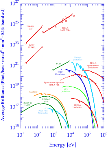
Figure 6: The double logarithmic graph of the (average) brilliance expressed as a function of photon energy for undulators and wigglers from several synchrotron light and FEL facilities. This graph is complementary to Figure 1 which would be out of scale (lower brilliance) in the present graph. Please note that the FEL output a photon flux is 9 orders of magnitude more brilliant compared to the highest of the synchrotron light facilities. [Image downloaded from https://photon-science.desy.de/research/students__teaching/sr_and_fel_basics/fel_basics/tdr_spectral_characteristics/index_eng.html]
REFERENCES:
[1] J. Weiner, F. Nunes, “Light-Matter Interaction: Physics and Engineering at the Nanoscale”, Oxford University Press, 2017
[2] WC. Röntgen, „Über eine neue Art von Strahlen“, Ann. Phys., 300, 12–17, 1898
[3] F. R. Elder, R. V. Langmuir and H. C. Pollock, “Radiation from Electrons Accelerated in a Synchrotron”, Phys. Rev., 74, 52, 1948
[4] https://lightsources.org/
[5] J. P.Blewett, “Synchrotron radiation — 1873 to 1947”, Nuclear Instruments and Methods in Physics Research Section A: Accelerators, Spectrometers, Detectors and Associated Equipment, 266, 1–3, 1988
[6] M. E. Couprie, “New generation of light sources: Present and future”, Journal of Electron Spectroscopy and Related Phenomena, 196, 2014
[7] Tsun-Kong Sham, “Chemical Applications of Synchrotron Radiation”, World Scientific, 2002
[8] J. R. Helliwell, “Macromolecular Crystallography with Synchrotron Radiation”, Cambridge, 2005
[9] E. Beaurepaire, H. Bulou, F. Scheurer and J. -P. Kappler, “Magnetism and Synchrotron Radiation”,Springer 2010
[10] G. E. Brown Jr., An Overview of Synchrotron Radiation Applications to Low Temperature Geochemistry and Environmental Science”, Reviews in Mineralogy and Geochemistry”, 49 (1), 1–115, 2002
[11] S. Ishihara, “Resonant X-ray scattering in manganites: Study of the orbital degree of freedom,” Rep. Prog. Phys., 65, 561–598, 2002
[12] W. Reimers, “Neutrons and Synchrotron Radiation in Engineering Materials Science”, John Wiley and Sons, 2008
[13] Helmut Wiedemann, “Particle accelerator physics”, Springer, 2007
[14] D. H Bilderback, “Review of third and next generation synchrotron light sources”, J. Phys. B: At. Mol. Opt. Phys., 38, 2005
[14a] Jui-Che Huang, “Challenges of in-vacuum and cryogenic permanent magnet undulator technologies,” Physical Review Accelerators and Beams, 20,064801, 2017
[15] D. H. Tomboulian and P. L. Hartman, “Spectral and Angular Distribution of Ultraviolet Radiation from the 300-Mev Cornell Synchrotron”, Phys. Rev. 102, 1423, 1956
[16] Ivan A. Vartanyants, “Synchrotron Light Sources and Free-Electron Lasers”, Springer, 2016
[17] G. Geloni, “Transverse coherence properties of X-ray beams in third-generation synchrotron radiation sources”, Nucl. Instrum. Meth. A, 588:463-493, 2008
[18] Brian W. J. McNeil, “X-ray free-electron lasers”, Nature Photonics, 4, 814–821, 2010
[19] K. Holldack, “Single bunch X-ray pulses on demand from a multi-bunch synchrotron radiation source”, Nature Communications, 5, 4010, 2014