Wires
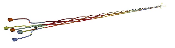
Wires and cables play an important role in modern aerospace and automotive industries. The electromagnetic interference between wires and cables may affect the normal operation of equipment and is therefore crucial to develop methodologies that can accurately predict coupling strength between wires and cables. Under the grant ICENITE we developed a range of geometrical models for routing of wires, cables and bundles. These are then directly meshed and simulated. Our numerical results for coupling between wires agrees excellently with our experimental measurements.
Textile Antennas
Wearable textile systems are receiving increased attention in healthcare, entertainment and the sports industry. Design and integration of an antenna within the clothing is a crucial aspect in the overall system design and has prompted increased research in fabric-based conductive and dielectric materials. Microstrip patch antennas are of particular interest as the ground plane shields the body from radiation. Regular deformations such as bending into a cylinder are well understood but little is known how arbitrary deformations of antenna surface, such as twisting and stretching, affect the resonant frequency and the beamwidth of antenna. We use computer graphics technique, Green Coordinate (GC), for space manipulations of three-dimensional (3D) objects to generate arbitrarily deformed antennas and investigate their impact on antenna properties. In particular we are looking into how small amount of crumpling and twisting affect the antenna parameters. For more info see the paper
A.Vukovic, S. Zongyuan, P. Sewell, L. A. Aziz, T. M. Benson, “Geometric Challenges of Modelling Textile Antennas”, European Modelling Symposium (EMS) 2017.
https://ieeexplore.ieee.org/document/8356787/
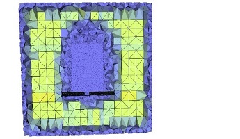
Examples of arbitrary deformation of a textile antenna
Installed Antennas
Modelling of installed antennas is a challenging task as it requires accurate geometry acquisition of both an antenna and a platform which may differ in size by several orders of magnitude. This is further complicated by the presence of complex inhomogeneous structures and non-linear and anisotropic materials. Moreover, antennas for many applications such as, 5G mobile and radar, come in the form of large arrays, where both mutual coupling between different antenna elements and the antenna array and the platform needs to be accurately accounted for. It is immediately obvious that such problems are multiscale in nature and as a consequence, are computationally demanding.
To reduce these multiscale requirements a common approach is to replace the intricate detail of antenna by a simpler model, or use domain decomposition techniques or using hybrid methods. The main disadvantage of such approaches is that they decouple an antenna from its practical setting and hence the near-field interactions between antenna and the platform are not properly accounted for.
In this case study UTLM is used for modelling of antennas installed on moderate and large size platforms in a fully coupled manner. This enables accurate prediction of antenna’s overall performance, including consideration of both near field parameters and radiation pattern of antenna. In the context of large simulations, graded size unstructured meshes can effectively discretisize both large and subwavelength features (as seen in pictures below) and can incorporate special multigridding techniques for particular features.

a) Crude tehtrahedral mesh
b) Volume mesh - fine mesh is used in the near field region of antenna and cubic mesh is used in the uniform regions.
Antenna in a Radome
Airborne radomes are weatherproof enclosures that protect an antenna from the physical environment and are designed to have minimal impact on the antenna performance. In practice, aerodynamic requirements for the radome profile cause degradation of antenna performance. then assesses how different radome profiles affect the antenna’s performance. The results show that a spherically blunted cone has the least influence on antenna’s performance and that super-spheroids can significantly change the antennas performance and need to be designed with care.

Comparison of antenna S11 parameter in the presence of different radome profiles.
Comparison of the antenna radiation pattern in the presence of different radomes for H-plane.
For more information please see the paper
A.Vukovic, P. Sewell, X. Meng, T. M. Benson, “Installed Antenna performance in Airborne radomes of Different Profiels”, ACES Express Journal paper, Vol.1, No.8, August 2016.
Link to paper: http://eprints.nottingham.ac.uk/46935/
Antenna in an airplane wing
The Vivaldi antenna is installed in a leading edge of an airplane wing. The wing is derived from NACA0010 airfoil and is made of perfect conductor. The impact of the wing platform and radome cover on antenna performance can be studied.
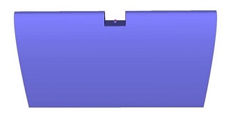 Antenna in a leading edge of the wing.
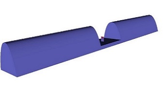 Antenna in a wing.
 Antenna far field pattern installed on a wing with and without dielectric radome cover.
Vivaldi array in a radome
The UTLM is used to investigate the mutual coupling between array elements with and without the radome cover in a fully coupled manner. 3x3 array of Vivaldi antennas is placed within a radome of ogive profile so that it is least disruptive to antenna radiation and S11 parameter. The array-radome set-up mimics a practical scenario where the radome is placed in the near field of a large antenna array. The EM simulation can provide a full set of S parameters showing mutual coupling between antennas and also the far field pattern of an array with and without the radome cover.

Surface mesh of the antenna elements and radome skin
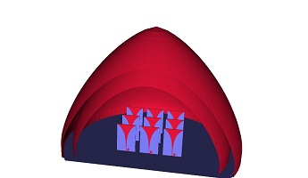
Antenna array in a radome (with radome cover)
For more information please see the paper – “Investigation Of Mutual Coupling In Vivaldi Antenna Arrays Installed In Airborne Radomes”, 12th European Conference on Antennas and Propagation, EuCAP London, 2018.)
Material Models:
CFC (Wind Turbine)
Plane wave incident on the wind turbine. The skin of the turbine is made of CFC material.

For more information on how the CFC material is implemented in UTLM please see the paper:
X. Meng, A. Vukovic, T. benson, P. Sewell, “Extended capability for Carbon Fiber Composite (CFC) Panels in the Unstructured Transmission Line Modelling (UTLM) Method”, IEEE Trans. EMC, Vol.58, No.3, June 2016.
https://ieeexplore.ieee.org/document/7429749/
https://arxiv.org/abs/1601.02241
Graphene Models
Information to follow.