
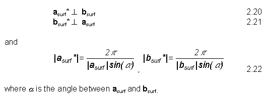
The basis vectors of the 2D reciprocal lattice, asurf* and bsurf* are related to the real space (also called direct space) surface lattice vectors, asurf and bsurf as follows:

where  represents a dot product. That is:
Note added 22/10/99: Note that in some surface science textbooks (notably Ertl and Kuppers) and literature the 2p factor is left out. Inclusion of this factor is useful in determining lattice spacings from LEED as the wavevector of the incident electrons in LEED is given by k=2p/l.
 Show that
the area of the reciprocal lattice unit cell is the inverse of the area of the real space unit cell.
A substrate basis vector in reciprocal space is defined by:

where h, k are Miller indices. We can write the basis vectors of the superstructure (asurf*, bsurf*) as:

That is;

The relationship between M and M* is:

Before going any further let’s sketch a few real space structures and their associated reciprocal lattices.
fcc(100)(1x1)
An easy example to start with! The real space lattice and basis vectors
are shown in Fig. 2.10(a). Using the relationships given in 2.20 - 2.22,
we see that the reciprocal lattice vectors (a* and
b*) in this case are parallel with the real space
lattice vectors and will have lengths given by 2p(|a| sin
(90))-1 and 2p(|b| sin
(90))-1. Thus with
|a|=|b|=1 the fcc(100)(1x1) reciprocal lattice (Fig. 2.10
(b)) is (symmetrically) identical to the real space lattice. (The only
difference is that the
length of the reciprocal lattice vectors is 2p)
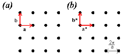
Fig. 2.10
 Sketch the RL for an fcc(111)(1x1) and an fcc(111)(2x1) structure.
The reciprocal lattice and LEED
Having illustrated how the real space and reciprocal space lattices are related, we’ll return to a discussion of the assertion at the start of this section: a LEED pattern is a direct representation of the surface reciprocal lattice.
A very important difference between x-ray diffraction as applied to 3D bulk solids and electron diffraction as applied to surfaces is that for the latter case translational symmetry perpendicular to the surface does not exist. To observe a Bragg diffraction spot in an x-ray diffraction experiment involving a 3D solid the following condition must be fulfilled:

where K| is the wavevector of the scattered X-ray, K is the wavevector of the incident x-ray and Ghkl is a (3D) reciprocal lattice vector.
Because a surface is periodic in only two dimensions, to observe a Bragg spot in a LEED experiment only the component of the wavevector parallel to the surface must be conserved with the addition of a (surface) reciprocal lattice vector. That is:

where Ghk is a reciprocal lattice vector as defined by 2.23 above. In LEED we thus have a much less stringent requirement for the observation of a diffraction pattern. This is made clearer if we consider the Ewald sphere construction as applied to bulk and surface diffraction. The Ewald sphere is a simple method of determining which diffraction spots we’ll observe for a particular energy of the incident x-rays or electrons and a particular experimental geometry.
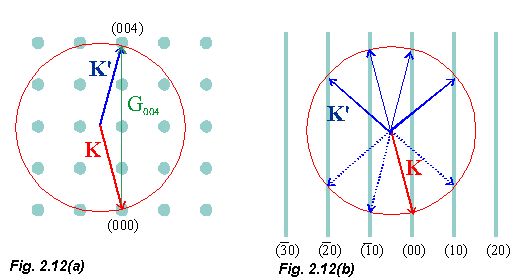
In Fig. 2.12(a), the Ewald sphere construction for a 3D case is shown.
We draw a vector K which terminates at the origin of reciprocal space and then construct a sphere of radius |K| (= , where
  is the wavelength of the incident electrons) about K. If a point on the reciprocal lattice lies on the surface of the sphere then 2.29 is satisfied and a Bragg diffraction spot is observed.
Fig. 2.12(b) represents the 2D case. You will see that the reciprocal lattice now consists of rods instead of points. Note that each rod is indexed with the appropriate values of h and k (see 2.23). One way of understanding why in the 2D case we observe rods instead of points is as described by Prutton, p. 56. Remember that separations in reciprocal space are inversely related to separations in real space. An alternative way of describing the loss of translational symmetry in the direction perpendicular to the surface (the z direction), is to say that the period in the z direction is infinite. This means that the points in reciprocal space have a separation of zero. So the reciprocal lattice rods consist of "zero spaced" i.e. densely packed reciprocal lattice points.
The presence of reciprocal lattice rods as opposed to points means that, unlike the bulk X-ray diffraction case, a LEED pattern will be observed over a very wide range of electron energies and geometries and thus we do not need to use techniques such as the Laue or Debye-Scherrer methods to produce a diffraction pattern. This can also be seen from the Ewald sphere construction. For bulk diffraction, it is only at certain discrete energies (i.e. values of |K|) that the sphere will intersect a RL point whereas for the 2D case diffraction is observed at all energies where the reciprocal lattice rod is within the sphere.
 What is the
spacing of the reciprocal lattice rods in Fig. 2.12(b) in terms of the real space surface lattice constant, |a|?
Simple examples of LEED pattern analysis
Nickel is an fcc metal whose (100) surface relaxes but does not reconstruct. For Ni(100) |a| = |b| = 2.48 Å. Take the incident electron energy to be 60 eV. Using the Ewald sphere construction, determine which Bragg diffraction spots should be observed.
The LEED pattern we observe at a particular energy will be given by the intersection of the reciprocal lattice rods with the Ewald sphere, whose radius is |K| =  , where
  is the wavelength of the incident electrons. The wavelength is related to the energy of the incident electrons via de Broglie’s relationship and therefore, following substitution of the appropriate values:

where  is the wavelength in Å and E is in eV. Thus, in this case, |K| = 3.97 Å-1.
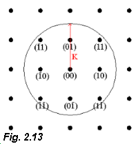 The reciprocal lattice is shown in Fig. 2.13. In this case we are looking
down on the lattice and seeing a "plan view" of the reciprocal lattice
rods. We draw a circle on the reciprocal lattice (representing a cross
section of the Ewald sphere), radius |K| whose centre is at the
origin of reciprocal space.
(Note that fig. 2.12(b) depicts K at an angle to the RL rods. Because LEED
studies are generally carried out with normal incidence of the electrons,
we can take the angle between K and the RL rods to be
0)
Note added 22/10/99: As discussed in the lecture of 18/10/99 this means that there is no inconsistency between having the tip of the incident wavevector at the origin of the RL and the centre of the Ewald sphere also fallign above the (00) RL point as shown in Fig. 2.13).
The RL rods that fall within the Ewald circle are indexed in Fig. 2.13 and will be those we observe in the LEED experiment.
From the angles the diffracted beams make with a particular real space direction we can evaluate the surface lattice constant. To see this refer to Fig. 2.12(b) and answer the following.
 Q. Remembering
that LEED experiments are usually carried out at normal incidence of the
electrons with the surface, show that for a simple square lattice:

where a is the real space lattice constant and  is the angle between the incident and diffracted electron beams.
 Describe
qualitatively the changes in the LEED pattern that occur as the incident electron energy is changed.
At this stage it is important to note that the LEED pattern is the Fraunhofer diffraction pattern - or the Fourier transform - of the surface lattice. Thus, just as in the optical diffraction case, a powerful method of converting between real and reciprocal space for surfaces is Fourier transformation.
You’ll cover this in one of the problems but an excellent site to visit for a tutorial on the relationships between Fourier transforms and diffraction is here
Adsorbate-induced superstructures
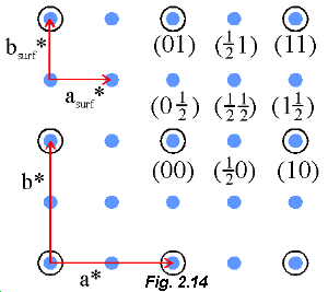 When 0.25 monolayer of oxygen is adsorbed onto the Cu(100) surface the LEED pattern changes to that shown in Fig. 2.14. The large open circles represent the LEED spots we observe before the adsorption of oxygen (cf Fig. 2.13) and the smaller blue circles are the spots that appear when 0.25 ML of O is present.
Note that we observe what are termed fractional order spots between the integral order spots arising from the substrate. The fractional order spots arise because O forms a superlattice on the surface with longer (real space) basis vectors than those of the substrate.
Hopefully Fig. 2.14 should look familiar (cf Fig. 2.11(b) )! You’ll see that the LEED pattern is a direct representation of the RL. In this case, it is possible just "by eye" to determine that the adsorption of 0.25 ML of oxygen on Cu produces a (2x2) superstructure. In Wood’s notation we denote this reconstruction as:
 Will the free
energy of the Cu(100) surface be higher or lower following adsorption of oxygen?
Stepping through LEED pattern analysis
Let’s work through the steps needed to convert the map of the reciprocal lattice provided by the LEED pattern (Fig.2.14) to the real space lattice (that is, if we don’t use Fourier transformation). From Fig. 2.14:

We now take the inverse transpose of M*, the first matrix on the right hand side of the equation above, to get the real space matrix, M.
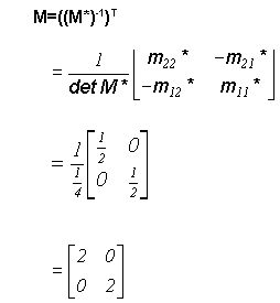
Therefore,

and we again see that 0.25 ML of oxygen forms a (2x2) superstructure on Cu(100).
LEED pattern analysis: surface structure
A very important point now arises. We’ve determined what the real space surface lattice is but this doesn’t tell us what positions the oxygen atoms adopt on the surface. To see this, consider the three arrangements of oxygen atoms shown in Fig. 2.15.
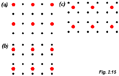
In (a) the oxygen atoms are situated directly above the Cu atoms, in (b) oxygen occupies what are termed bridge sites between Cu atoms, whereas in (c) the oxygen atoms are at the hollow sites between 4 Cu atoms. Although the adsorption sites differ considerably each arrangement will produce a (2x2) LEED pattern.
To distinguish between different bonding geometries (and to determine parameters such as the bond length and bond angle) an examination of the variation of LEED spot intensity as a function of electron energy is required. We will return to this point in Section 6 of the module.